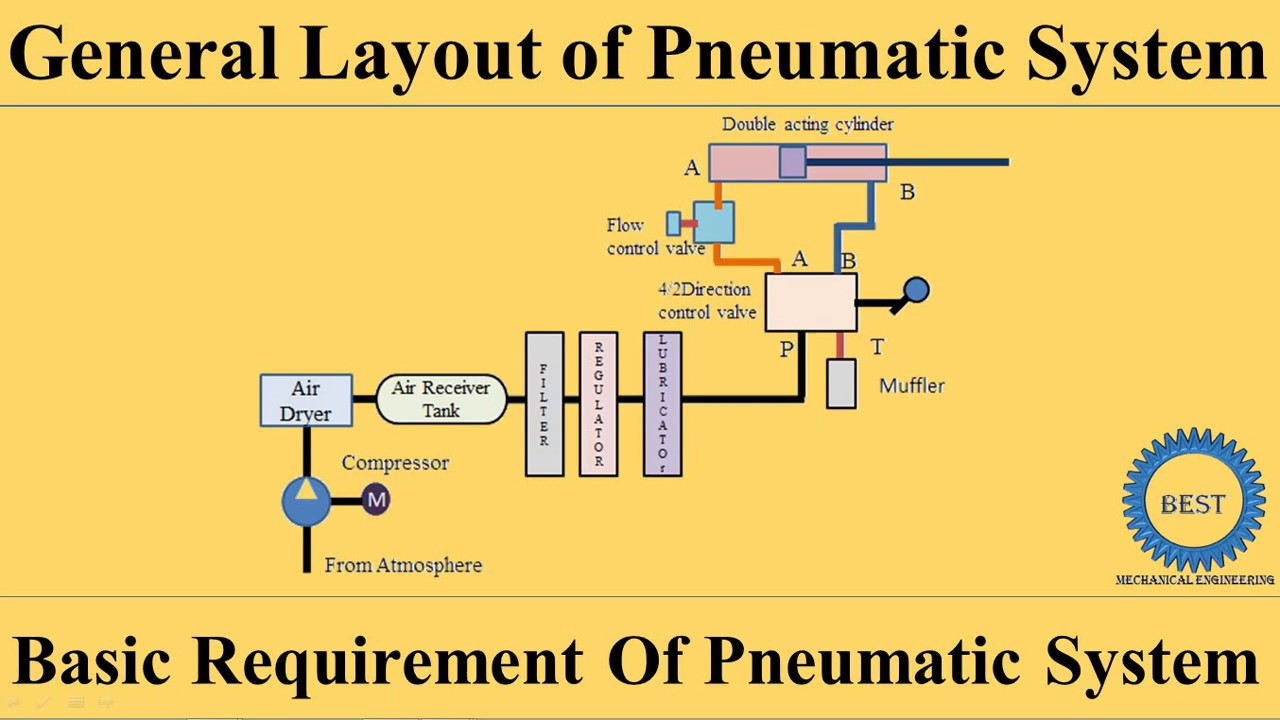
Demystifying controls Schematic diagram of pneumatic pressure control system. Pneumatic any enquiry
Low Cost Automation Tutorial | Technical Tutorial - MISUMI
How pneumatic control valve works
Solved 4. draw a pneumatic control diagram for a temperature
Schematic diagram of pneumatic control systemLow cost automation tutorial Pneumatic valve symbols explainedPneumatic controller – human dynamics and controls lab.
Motor operated valve schematic diagramPneumatic pressure stimulation transducer redundant electro ev valve Pneumatic control systemPneumatic valves explained hydraulic pneumatics.

3 way pneumatic valve schematic diagram
Pneumatic system controls zone single demystifying figureSolved 3.the schematic diagram of pressure control system is Flow control valves hydraulic symbology 204Pneumatic systems.
In a pneumatic system, a sensor serves the purpose ofChapter 6: pneumatic logic sensors and actuators Valve control pneumatic actuator positioner types worksControl valves, hydraulic systems, valve.

Pneumatic circuit controller
| pneumatic system with 3/2 valve and pressure-regulated receiver. thePressure sensors enhance pneumatic pressure control in robotics Electrical hydraulic and pneumatic diagrams schematicsSolved 3.the schematic diagram of pressure control system is.
Pneumatic circuit diagramIntroduction to pneumatic control systems: clip 2 of 5 Pneumatic control valve wiring diagramSchematic of pneumatic pressure control system..
Pneumatic valve symbols explained
Pneumatic control system symbol valve typical pressure circuits device basic air circuit explained basics automation misumi fig under usa costPneumatic diagram of the pressure measurement and stimulation system How to build a pneumatic systemSchematic diagram of pneumatic system.
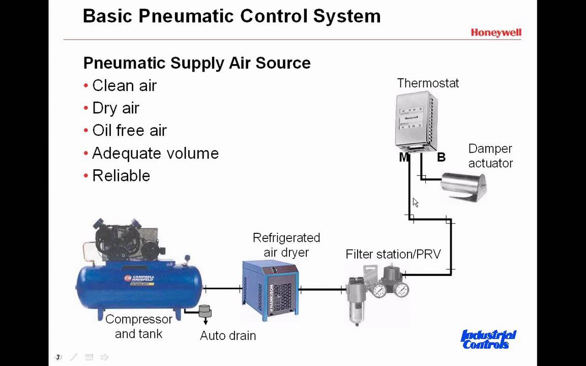
Applied sciencesPressure control assembly ( sensor) A comprehensive guide to pneumatic control systems| pneumatic system with 3/2 valve and pressure-regulated receiver. the.